


























Routers vs Switches vs Hubs vs Bridges: Key Differences
Routers, switches, hubs and bridges compared by OSI layer, forwarding logic, collision and broadcast domains, plus Linux, Docker and cloud equivalents.
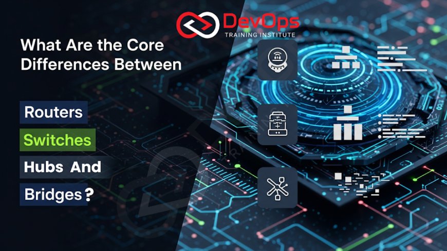
A hub repeats every signal to every port (OSI Layer 1). A bridge joins two LAN segments and forwards frames by MAC address (Layer 2). A switch is a multi-port bridge that sends each frame only to the port where the destination MAC lives (Layer 2). A router connects different IP networks and forwards packets by IP address (Layer 3).
These four devices map neatly onto the layers in our pillar guide, What Is the OSI Model?. This article explains how each device decides where traffic goes, how they divide collision and broadcast domains, and where you meet the same ideas in Linux, Docker and cloud networks as a DevOps engineer.
Key takeaways
- Hubs work at Layer 1 and have no addressing logic. They are obsolete in modern networks but still useful for understanding collisions.
- Bridges and switches work at Layer 2. They learn which MAC address sits behind which port and forward frames only where needed.
- Routers work at Layer 3. They read the destination IP address, look it up in a routing table and forward the packet toward the next hop.
- Every switch port is its own collision domain. Every router interface is its own broadcast domain.
- Linux can act as a bridge or a router. Docker's default
docker0network is a Linux bridge, and cloud VPC route tables do the job of a router.
Quick comparison
| Feature | Hub | Bridge | Switch | Router |
|---|---|---|---|---|
| OSI layer | 1 (Physical) | 2 (Data link) | 2 (Data link); Layer 3 switches also route | 3 (Network) |
| Forwards based on | Nothing; repeats bits | Destination MAC address | Destination MAC address | Destination IP address |
| Table it keeps | None | MAC address table | MAC address table (often called the CAM table) | Routing table, plus ARP cache |
| Typical ports | 4 to 24 | 2 (classic bridge) | 8 to 48 or more | 2 or more interfaces |
| Collision domains | One shared across all ports | One per side | One per port | One per interface |
| Broadcast domains | One | One | One per VLAN | One per interface |
| Duplex | Half duplex only | Half or full | Full duplex per port | Full duplex |
| Connects different networks? | No | No, same network | No (unless Layer 3) | Yes |
| Still sold today? | Rarely | As a function, not a box | Yes | Yes |
Hubs: repeat everything
A hub is a multi-port repeater. Electrical signals arriving on one port are regenerated and sent out of every other port. The hub does not read frames, so it has no idea which device a frame is for. Every connected device receives every frame and its network card discards the ones not addressed to it.
Because all ports share one medium, only one device can transmit at a time. If two transmit together, their signals collide. Classic Ethernet handled this with CSMA/CD (carrier sense multiple access with collision detection): devices listen before sending, detect collisions, and wait a random time before trying again. As more devices join a hub, collisions increase and usable throughput drops.
Hubs also run half duplex only, which means a device cannot send and receive at the same moment. Modern switched Ethernet runs full duplex, so CSMA/CD is not used on switch links. You will rarely find a hub in a working network today, but hub behaviour explains why switches replaced them.
Bridges: split a segment in two
A bridge connects two LAN segments and decides, frame by frame, whether a frame needs to cross. It does this by learning:
- When a frame arrives, the bridge records its source MAC address and the port it came in on.
- It looks up the destination MAC address in its table.
- If the destination is on the same side as the source, the bridge drops (filters) the frame.
- If the destination is on the other side, the bridge forwards it.
- If the destination is unknown, or it is a broadcast, the bridge floods it to the other side.
This splits one collision domain into two, which cut collisions on busy shared segments. Bridges do not split broadcast domains: a broadcast such as an ARP request still reaches both sides.
Transparent bridging and the Spanning Tree Protocol were originally defined in IEEE 802.1D; that material is now part of IEEE 802.1Q. Spanning tree matters because if two bridges create a loop, broadcast frames circulate forever. STP (and the faster RSTP) blocks redundant links until they are needed.
Standalone two-port bridges have disappeared as products, but the bridge function is everywhere: in every switch, in wireless access points that bridge Wi-Fi to Ethernet, and in the Linux kernel.
Switches: a bridge with many ports
A switch applies the same learning and forwarding logic as a bridge, but on every port and in hardware. Each port gets its own collision domain, and with full duplex links there are no collisions at all. Many devices can talk at the same time, each at full port speed, because the switch forwards frames between pairs of ports in parallel.
Key switch features you will meet:
- MAC address table: entries age out after a timeout (300 seconds is a common default) so the table reflects devices that move.
- VLANs (IEEE 802.1Q): one physical switch can be split into several logical switches. Each VLAN is a separate broadcast domain, and traffic between VLANs needs a router or Layer 3 switch.
- Trunk ports: carry several VLANs on one link using 802.1Q tags.
- Managed versus unmanaged: unmanaged switches just forward; managed switches add VLANs, link aggregation, port security, SNMP and mirroring.
- Layer 3 switches: route between VLANs in hardware. They blur the line between switch and router inside a campus or data centre, though they usually lack the WAN features, NAT and firewalling of a dedicated router.
The physical layout of switches is a topology choice. Our posts on star vs mesh topology and ring and bus topologies explain why switched star networks became the default.
Routers: move packets between networks
A router connects separate IP networks, such as your office LAN and your internet provider, or two subnets in a data centre. For each packet it:
- Reads the destination IP address.
- Finds the most specific matching route in its routing table (longest prefix match).
- Decrements the TTL (IPv4) or hop limit (IPv6) and drops the packet if it reaches zero.
- Uses ARP (IPv4) or Neighbor Discovery (IPv6) to find the MAC address of the next hop, rewrites the Layer 2 header, and sends the packet out of the right interface.
The IP addresses stay the same across the path (unless NAT changes them). The MAC addresses change at every router hop. This is the clearest way to see the difference between Layer 2 and Layer 3.
Routes come from three places: directly connected networks, static routes an administrator adds, and dynamic routing protocols such as OSPF and BGP. Routers do not forward broadcasts between interfaces, so each interface is its own broadcast domain. That is why subnetting with routers between subnets limits broadcast traffic and creates natural security boundaries. IETF RFC 1812 sets out the requirements for IPv4 routers.
A home "router" is usually several devices in one box: a router, a small switch, a Wi-Fi access point, a DHCP server, NAT and a basic firewall.
Following one packet through all four
Imagine a laptop on an office network opening a website. The laptop is plugged into a switch, the switch connects to the office router, and the router connects to the internet.
- The laptop sees the website's IP address is not in its own subnet, so it sends the packet to its default gateway (the router). It uses ARP to learn the router's MAC address, then builds a frame addressed to that MAC.
- The switch reads the destination MAC, finds the router's port in its MAC table and sends the frame only there. Other devices on the switch never see it. (On a hub, every device would have received a copy.)
- The router strips the frame, reads the destination IP, finds its default route toward the provider, applies NAT to replace the private source address, builds a new frame for the provider's next-hop MAC and sends it.
- The reply comes back the same way in reverse: the router translates the address back and forwards the packet onto the LAN, and the switch delivers it to the laptop's port.
The protocols at each step (Ethernet, ARP, IP, TCP, HTTP) are listed layer by layer in our protocols at each OSI layer reference.
Collision and broadcast domains in one table
| Network | Collision domains | Broadcast domains |
|---|---|---|
| 8 PCs on one hub | 1 | 1 |
| Two hubs of 4 PCs joined by a bridge | 2 | 1 |
| 8 PCs on one switch (no VLANs) | 8 | 1 |
| 8 PCs on one switch with 2 VLANs | 8 | 2 |
| Two switches of 4 PCs each, joined by a router | 8 PC ports plus the 2 router links | 2 |
Questions like these appear often in networking interviews. Our CCNA interview FAQs include more of them.
Where DevOps engineers meet these devices
You may never rack a switch, but the same concepts run inside the servers and clouds you manage.
Linux as a bridge
The Linux kernel has a software bridge. Docker's default network creates a bridge called docker0 and connects each container's virtual Ethernet (veth) interface to it, so containers on one host talk at Layer 2. KVM hosts use bridges the same way for virtual machines.
# show bridges and the interfaces attached to them
ip link show type bridge
bridge link show

# create a bridge and attach an interface (lab use)
sudo ip link add br0 type bridge
sudo ip link set eth1 master br0
sudo ip link set br0 up
Linux as a router
Any Linux host with IP forwarding turned on routes packets between its interfaces. Kubernetes nodes rely on this for Pod traffic, and NAT rules (through iptables or nftables) let containers reach the internet through the host's address.
# check and enable IPv4 forwarding
sysctl net.ipv4.ip_forward
sudo sysctl -w net.ipv4.ip_forward=1

# view the routing table and look up the route for an address
ip route show
ip route get 8.8.8.8
On RHEL, network interfaces and routes are managed with NetworkManager; see configuring networking in RHEL 10.
Cloud networks
In a cloud VPC or VNet you do not see switches or routers, but route tables, subnets, internet gateways and NAT gateways do the same jobs. A subnet behaves like a broadcast-free Layer 2 segment managed by the provider, and the route table is the router. Our guide to cloud networking concepts for DevOps engineers maps each physical device to its cloud equivalent.
Device-to-cloud mapping
| Physical device | Linux / container equivalent | Cloud equivalent |
|---|---|---|
| Hub | None in normal use | None |
| Bridge / switch | Linux bridge, Open vSwitch, docker0 | Subnet fabric managed by the provider |
| Router | Host with ip_forward=1, routing table | VPC route table, internet gateway, transit gateway |
| Router with NAT | iptables/nftables masquerade | NAT gateway |
Troubleshooting by layer
| Symptom | Layer to check | Useful command |
|---|---|---|
| Link light off, interface down | 1 (cable, port) | ip link show |
| Can reach nothing on the same subnet | 2 (switch port, VLAN, ARP) | ip neigh show |
| Same subnet works, other networks fail | 3 (gateway, routes) | ip route get <ip>, tracepath |
| Network reachable, service not | 4 and above (ports, firewall) | ss -tlnp |
Learn networking for DevOps
Networking basics are part of our Linux administration training, where you configure interfaces, routes and bridges on real systems, and they carry into container and cloud networking in our DevOps training. Both run in the Kharadi, Pune classroom and live online.
Frequently asked questions
What is the main difference between a switch and a router?
A switch forwards frames within one network using MAC addresses (Layer 2). A router forwards packets between different networks using IP addresses (Layer 3). Switches connect devices; routers connect networks.
Is a bridge the same as a switch?
Functionally, a switch is a multi-port bridge. Both learn MAC addresses and forward frames at Layer 2. Classic bridges had two ports and worked in software; switches have many ports and forward in hardware.
Why are hubs no longer used?
Hubs send every frame to every port, run only half duplex, and share one collision domain, so performance falls as devices are added and any device can see all traffic. Switches fix all of these problems and cost about the same.
What is a Layer 3 switch?
A Layer 3 switch is a switch that can also route between VLANs or subnets in hardware. It is common inside campuses and data centres, while dedicated routers handle WAN links, NAT and advanced routing.
Does a router break up broadcast domains?
Yes. Routers do not forward broadcasts between interfaces, so each router interface is a separate broadcast domain. VLANs on a switch also create separate broadcast domains.
Which OSI layer does each device work at?
Hubs work at Layer 1, bridges and switches at Layer 2, and routers at Layer 3. Layer 3 switches work at both Layer 2 and Layer 3.
Is Docker's bridge network a real bridge?
Yes. Docker's default network uses a Linux kernel bridge named docker0. Each container connects through a veth pair, and the bridge forwards frames between containers by MAC address, just like a switch.
References
What's Your Reaction?
 Like
0
 Dislike
0
 Love
0
 Funny
0
 Angry
0
 Sad
0
 Wow
0